Dataset v1.0 Open Access (Registration Required) Yokohama, Japan

Sub-6GHz MIMO Channel Sounding Dataset

Double-directional 8×8 MIMO channel measurements in urban outdoor environments at 4.850 GHz, collected in Yokohama City, Japan. Supports 5G/6G channel modeling, beamforming research, and propagation analysis.

4.850 GHz
Frequency Band
8 × 8
MIMO Configuration
3,386
Valid Samples (Total)
4
Campaigns
LoS / NLoS
Propagation Labels
.mat / .csv
Data Format

Dataset Overview

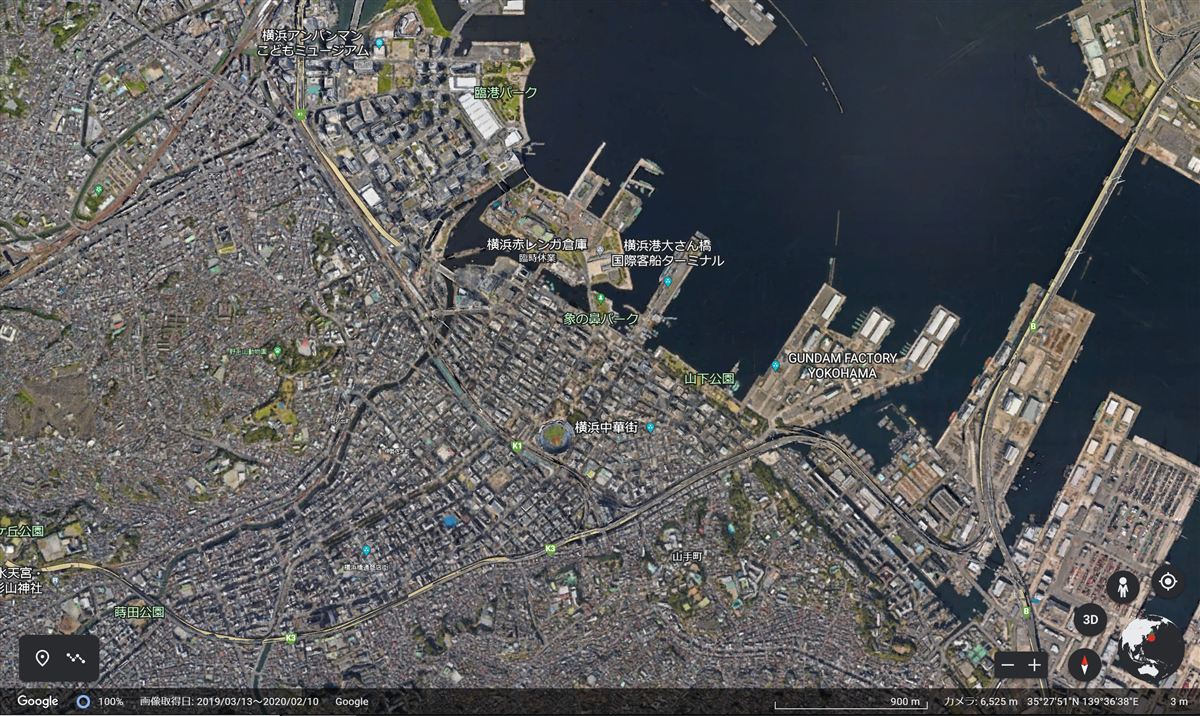
This dataset was collected by the Radio Signal Processing Laboratory at Niigata University as part of drive measurement campaigns in urban macro-cell (UMa) and micro-cell (UMi) environments in Yokohama City, Japan. Four routes (R3, R4, R5, R6) were driven across three distinct areas: Yuraku, NTTCom, and World Porters (WP).

Each drive covers 3,000 measurement points (sample period: 0.512 s) with co-located 360° panoramic photos (every 10 s, ~150 pcs per route). Valid samples are selected based on vehicle motion, TX field-of-view, and power threshold criteria.

Measurement Setup

Frequency4.850 GHz
Measurement TypeDouble-directional channel measurement
TX Antenna8-Element Uniform Linear Array (ULA)
RX Antenna8-Element Uniform Circular Array (UCA)
Sample Period0.512 s  ·  3,000 pts / route
Panorama PhotosEvery 10 s  ·  ~150 pcs / route
EnvironmentsUrban macro-cell (UMa), Urban micro-cell (UMi)
LocationYokohama City, Japan
Channel SounderMIMO Channel Sounder

Measurement Campaigns

R3 – Yuraku (UMa)
Drive ID: 20221201_Yuraku_004  ·  915 valid / 3,000 pts  ·  41 photos
Urban Macro 4.850 GHz
R4 – NTTCom (UMa)
Drive ID: 20221202_NTTCom_001  ·  634 valid / 3,000 pts  ·  25 photos
Urban Macro 4.850 GHz
R5 – NTTCom (UMa)
Drive ID: 20221202_NTTCom_002  ·  102 valid / 3,000 pts  ·  6 photos
Urban Macro 4.850 GHz
R6 – WP / World Porters (UMi)
Drive ID: 20221201_WP_001  ·  1,735 valid / 3,000 pts  ·  15 photos
Urban Micro 4.850 GHz

Measurement Method

Channel measurements were performed using a custom-built 8×8 full-array MIMO channel sounder capable of simultaneous dual-band operation at 2.4 GHz and 4.8 GHz. The system was designed for drive measurements (mobile receiver mounted on a vehicle), enabling large-scale data collection across urban environments.

Channel Sounder System
ParameterValue
Carrier Frequency2.462 / 4.850 GHz
Signal Bandwidth40 / 100 MHz
Delay Resolution25 / 10 ns
Sounding SignalMultitone (N = 200 / 510)
FFT Points4,096
Sampling Rate800 MSa/s
Delay Span5.12 μs
TX Power~23 dBm / antenna
BS Antenna8-element ULA (6.5 dBi, 75° HPBW)
MS Antenna8-element UCA (4.0 dBi, 90° HPBW)
FDM+STDM Hybrid Multiplexing

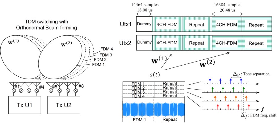
The 8×8 MIMO channel matrix is sounded using a hybrid FDM+STDM (Frequency Division Multiplexing + Space-Time Division Multiplexing) scheme [Kim et al., 2012]. Within each 4-antenna unit, the four TX signals occupy different sub-bands (FDM). The two 4-element units are then switched sequentially via STDM with orthonormal beamforming weights, completing a full 8×8 channel measurement in a single 100 μs symbol duration — fast enough for continuous drive measurement.

FDM+STDM hybrid multiplexing diagram

FDM+STDM hybrid multiplexing: two TX units (Utx1/Utx2) are switched via TDM with orthonormal beamforming weights, each carrying 4 FDM sub-channels. One full frame measures the complete 8×8 MIMO channel.

Back-to-Back Calibration

A back-to-back (B2B) calibration procedure is applied to eliminate the frequency-dependent transfer characteristics of the TX and RX hardware chains. The calibration response — measured by connecting TX and RX directly — is divided out of each measured transfer function, yielding calibrated channel frequency responses.

Channel Sounder Hardware
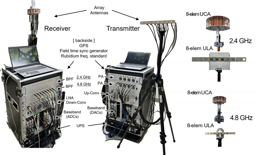
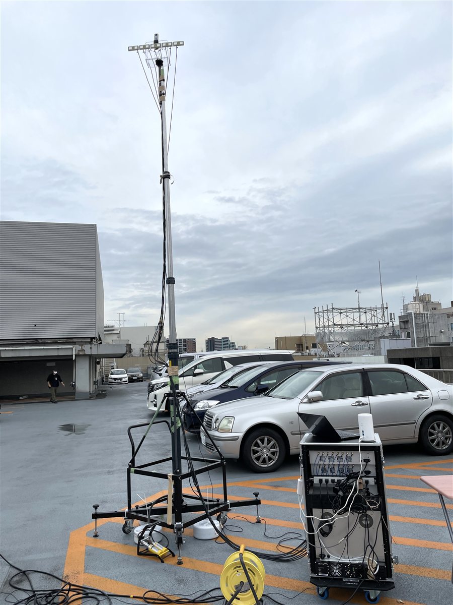
8×8 MIMO channel sounder system

TX and RX racks of the 8×8 MIMO channel sounder with 8-element UCA and ULA array antennas for 2.4 GHz and 4.8 GHz bands.

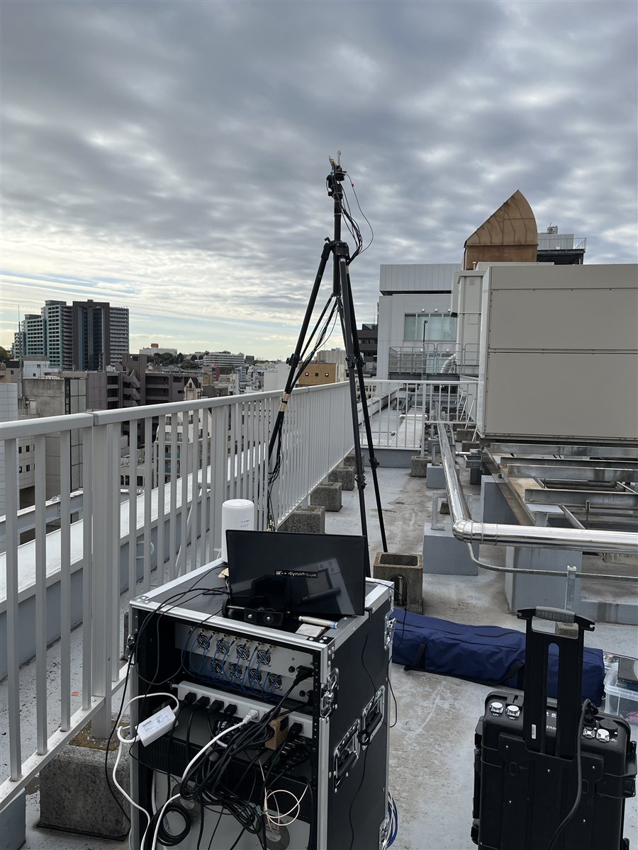
BS Installation (Yokohama)
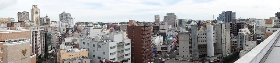
BS rooftop panoramic view, Yokohama

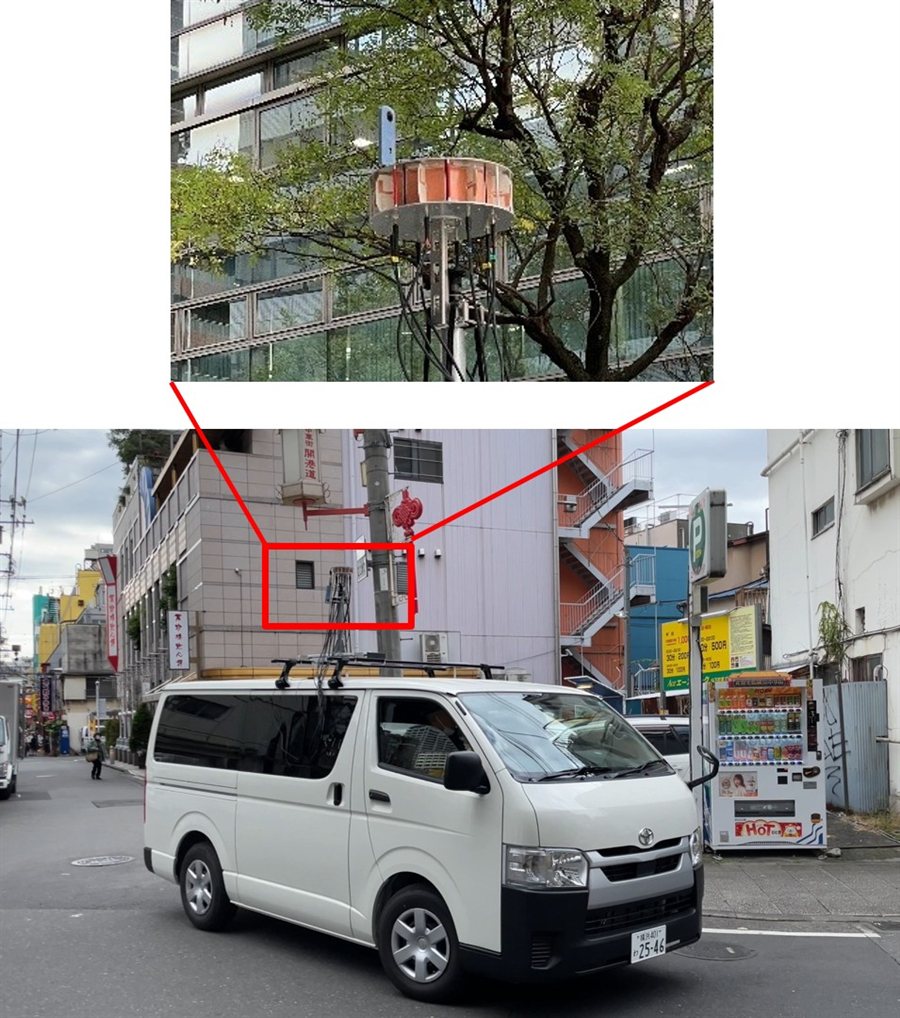
Panoramic view from the BS rooftop installation (Yokohama city). The 8-element ULA antenna was mounted at building heights of 33–34 m (UMa) and 3 m (UMi).

Scenarios

Scenario Area / BS Location BS Antenna BS Height Direction Routes
Urban Macro
UMa
Kanai Area
Yokohama Daiichi Yuraku Bldg.
8-elem ULA 33 m N R3
China Town
NTTCom Yokohama Yamashita Bldg.
8-elem ULA 34 m SE R4R5
Urban Micro
UMi
Streets
Yokohama World Porters
8-elem UCA 3 m R6
MS Antenna
MS Antenna (common to all areas)
8-Element Uniform Circular Array (UCA) · Height: 2.7 m · Mounted on vehicle roof
Area 1 – Yuraku Environment

BS Antenna

BS Antenna – Yuraku

MS Antenna

MS Antenna
Area 1 – Yuraku UMa
LocationKanai Area, Yokohama
BS BuildingYokohama Daiichi Yuraku Bldg.
BS Antenna8-elem ULA
BS Height33 m
BS DirectionNorth (N)
RoutesR3
Valid Samples915 (R3, 4.85 GHz)
Area 2 – NTTCom Environment

BS Antenna

BS Antenna – NTTCom

MS Antenna

MS Antenna
Area 2 – NTTCom UMa
LocationChina Town, Yokohama
BS BuildingNTTCom Yokohama Yamashita Bldg.
BS Antenna8-elem ULA
BS Height34 m
BS DirectionSouth-East (SE)
RoutesR4, R5
Valid Samples634 (R4) + 102 (R5)
Area 3 – WP Environment

BS Antenna

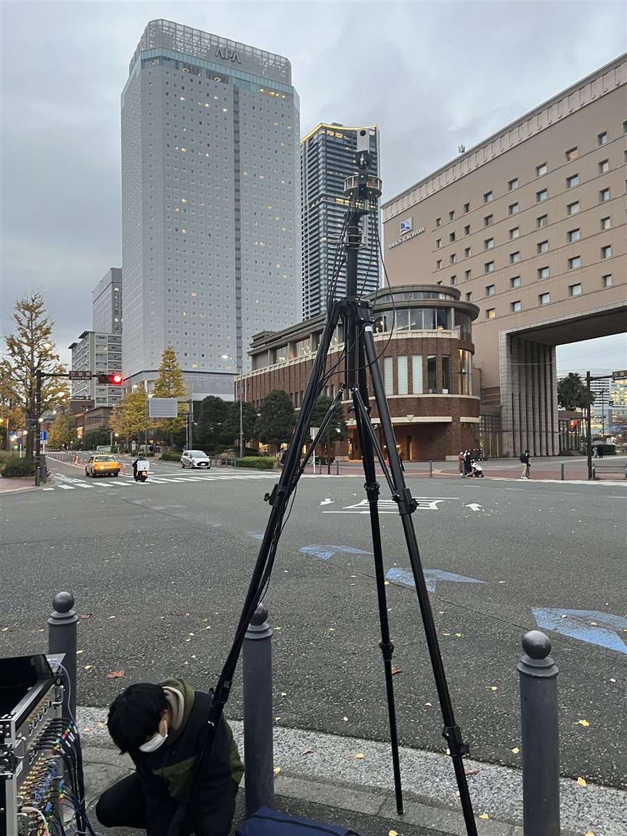
BS Antenna – WP

MS Antenna

MS Antenna
Area 3 – World Porters UMi
LocationYokohama World Porters
BS PlacementStreet-level
BS Antenna8-elem UCA
BS Height3 m
RoutesR6
Valid Samples1,735 (R6, 4.85 GHz)

Data Preview

Sample visualizations of the measurement campaigns.

R3 – Yuraku (Urban Macro) R6 – WP (Micro Cell) R4 – NTTCom (Urban Macro) R5 – NTTCom (Urban Macro) Actual GPS measurement routes

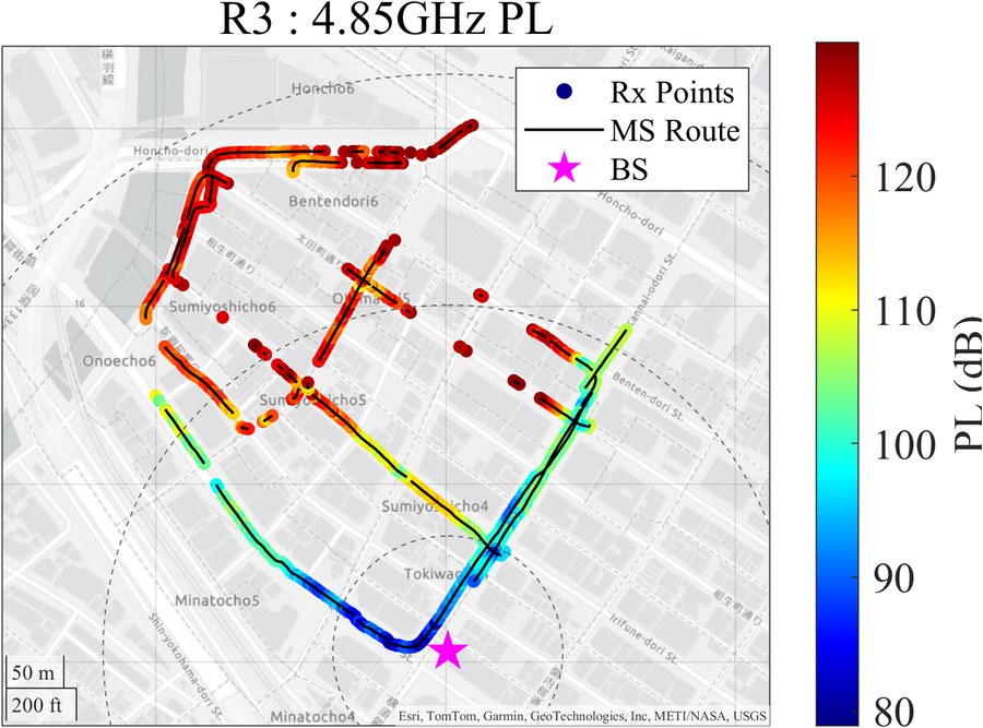
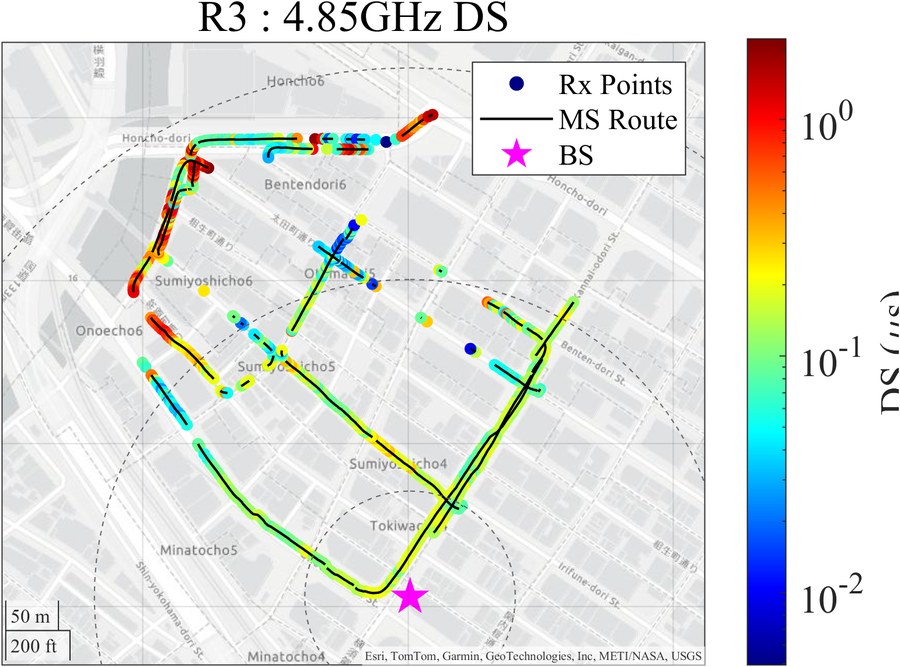
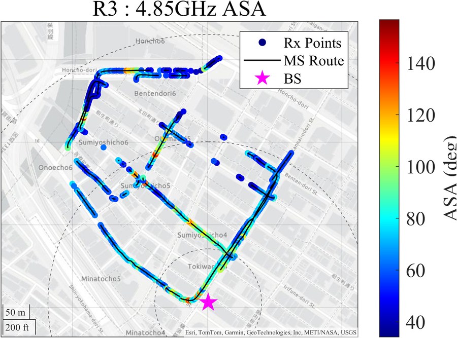
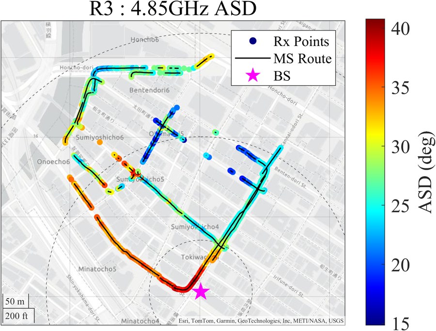
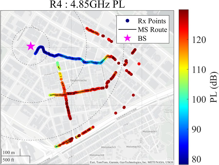
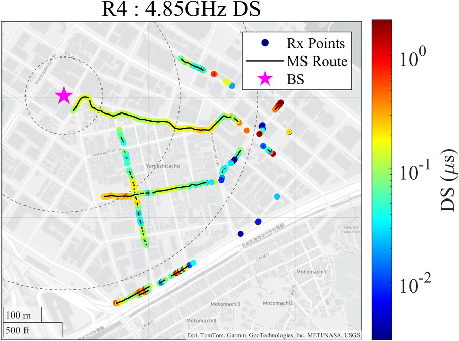
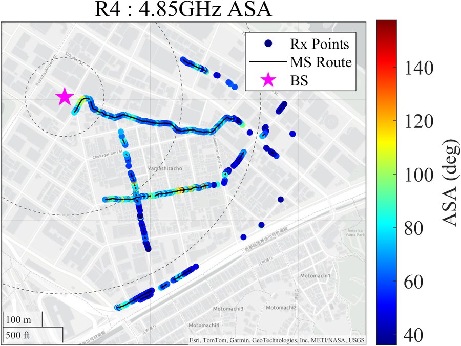
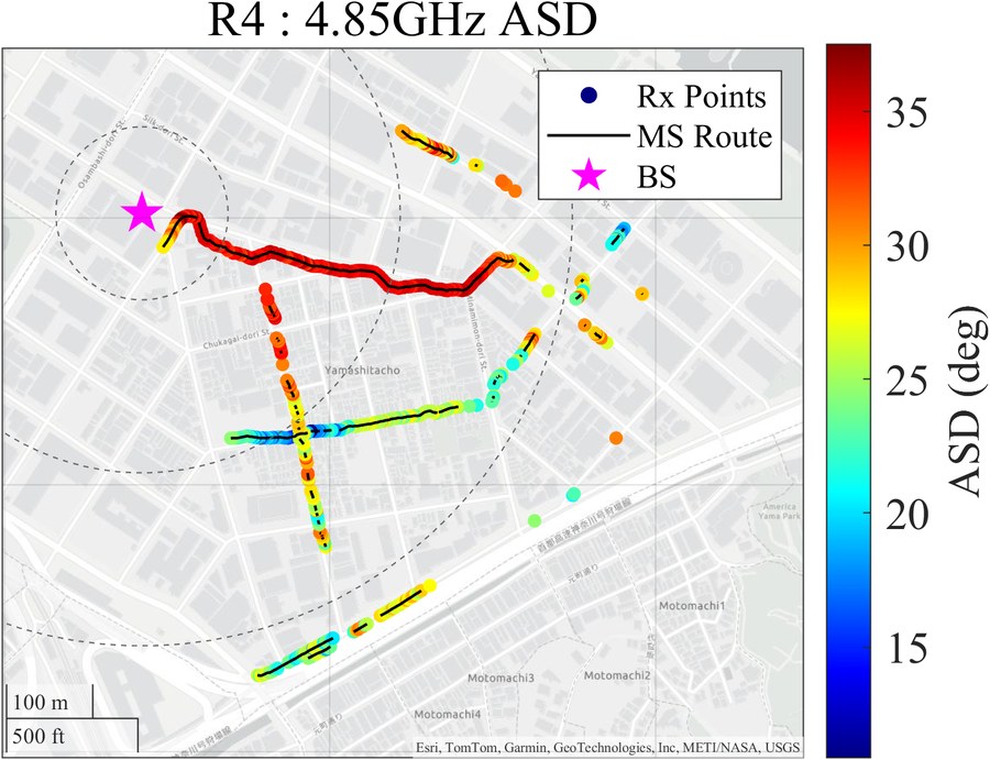
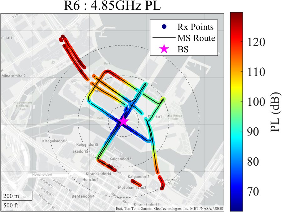
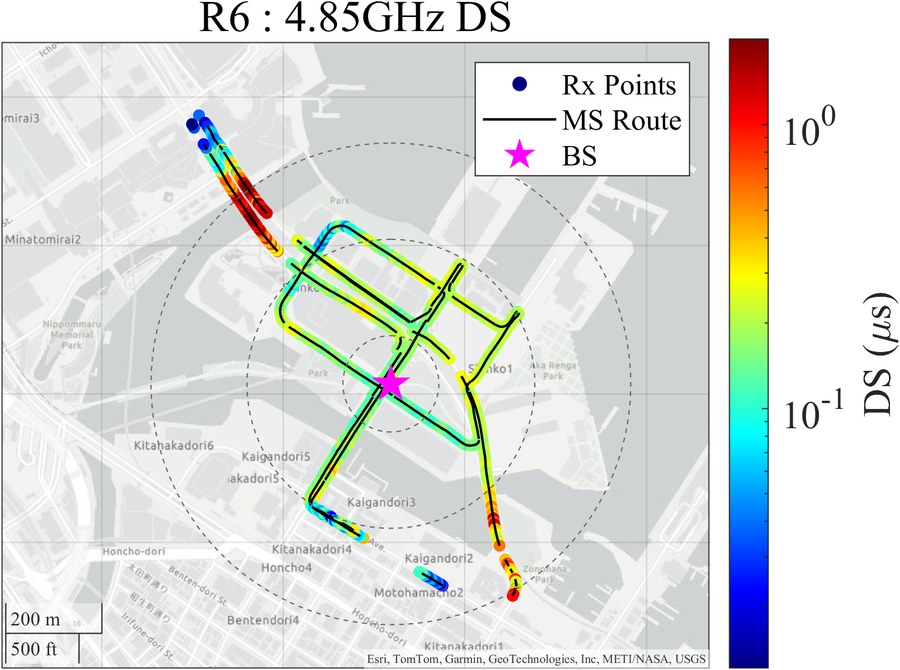
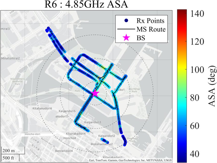
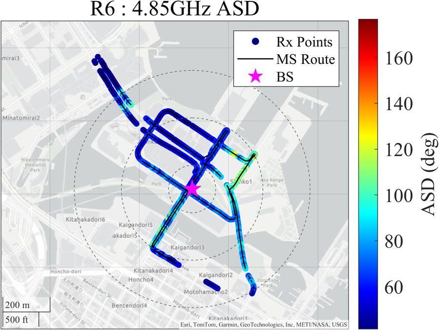
Route map of Large Scale Parameters (PL, DS, ASA, ASD) at 4.850 GHz.

PL

R3 PL

DS

R3 DS

ASA

R3 ASA

ASD

R3 ASD

R3 – Yuraku (Urban Macro, Area 1) · 915 valid samples

PL

R4 PL

DS

R4 DS

ASA

R4 ASA

ASD

R4 ASD

R4 – NTTCom (Urban Macro, Area 2) · 634 valid samples

PL

R6 PL

DS

R6 DS

ASA

R6 ASA

ASD

R6 ASD

R6 – WP / World Porters (Urban Micro, Area 3) · 1,735 valid samples

Campaign Summary
RouteAreaScenarioMeas. Points (LoS/NLoS)Valid Points (LoS/NLoS)Photos
R3Yuraku (Area 1)UMa137 / 2,86369 / 84641
R4NTTCom (Area 2)UMa243 / 2,757182 / 45225
R5NTTCom (Area 2)UMa— / 1026
R6WP (Area 3)UMi1,419 / 1,581827 / 90815
Total3,38687

Measured channel statistics at 4.85 GHz. CI = Close-In model, FI = Floating-Intercept model. n: PLE, σ: shadow fading std. dev. (dB).

Path Loss Parameters
RouteScenarioState CI Model FI Model
nσ αβσ
Area1UMaLoS2.313.701.9852.593.67
NLoS2.894.502.9145.454.50
Area2UMaLoS1.942.731.8248.932.72
NLoS2.903.741.2190.133.38
Area3UMiLoS2.044.412.5535.264.10
NLoS2.687.324.61-1.016.66
Large-Scale Parameters (LSP) at 4.85 GHz

Mean μ and std. dev. σ of log₁₀ values. 3GPP values from TR 38.901.

Parameter Area1 (UMa) Area2 (UMa) 3GPP UMa Area3 (UMi) 3GPP UMi
LoSNLoS LoSNLoS LoSNLoS LoSNLoS LoSNLoS
RMS DS
log₁₀(DS/1s)
μ −6.993−6.882 −6.995−6.944 −6.958−7.002 −6.934−6.811 −6.481−6.633
σ 0.180.28 0.350.31 0.660.70 0.280.33 0.390.32
RMS ASD
log₁₀(ASD/1°)
μ 1.4100.548 0.656−0.345 1.0791.485 1.7651.616 1.2811.251
σ 0.043.82 3.695.26 0.300.45 0.131.25 0.230.34
RMS ASA
log₁₀(ASA/1°)
μ 1.6490.812 0.852−0.084 1.8102.030 1.5541.467 1.2211.421
σ 0.163.89 3.745.36 0.200.31 0.141.24 0.160.26
K-factor (dB) μ −0.82 2.51 9.00 0.69 9.00
σ 2.72 3.00 3.50 3.01 5.00

Drive measurement video clips at 4.850 GHz. Each clip shows the measurement route with real-time channel data overlay.

R3 – Yuraku (Urban Macro, Area 1) · 4.850 GHz · 915 valid samples

R4 – NTTCom (Urban Macro, Area 2) · 4.850 GHz · 634 valid samples

R5 – NTTCom (Urban Macro, Area 2) · 4.850 GHz · 102 valid samples

R6 – WP / World Porters (Urban Micro, Area 3) · 4.850 GHz · 1,735 valid samples

Available Files

File Name Contents Format Size
R1_Yuraku_2.4GHz.zip Campaign R1 channel transfer functions .mat — MB Requires registration
R3_Yuraku_4.8GHz.zip Campaign R3 channel transfer functions .mat — MB Requires registration
R6_WP_4.8GHz.zip Campaign R6 channel transfer functions .mat — MB Requires registration
README.txt Data structure, field descriptions, MATLAB usage guide .txt — KB Requires registration

Download

This dataset is freely available for academic and research purposes. Please complete the registration form below. The download link will be provided immediately after submission.

Citation

If you use this dataset in your research, please cite the following paper:

@article{tsukada2025millimeter,
  author  = {Tsukada, Hibiki and Suzuki, Naoya and
             Bag, Banibrata and Takahashi, Riku and
             Kim, Minseok},
  title   = {{Millimeter-Wave Urban Cellular Channel
             Characterization and Recipe for
             High-Precision Site-Specific Channel
             Simulation}},
  journal = {IEEE Transactions on Vehicular Technology},
  volume  = {74},
  number  = {3},
  pages   = {3598--3612},
  year    = {2025},
  doi     = {10.1109/TVT.2024.3492719}
}

@article{calist2025bridging,
  author  = {Calist, Inocent and Kim, Minseok},
  title   = {{Bridging FR1 to FR3: Urban Channel
             Parameterization Anchored at 4.85 GHz
             and Literature-Referenced Cross-Band
             Trends}},
  journal = {arXiv preprint},
  year    = {2025},
  eprint  = {2512.00707},
  url     = {https://arxiv.org/abs/2512.00707}
}

@article{zhang2026environment,
  author  = {Zhang, Xuejian and He, Ruisi and
             Kim, Minseok and Calist, Inocent and
             Yang, Mi and Qi, Ziyi},
  title   = {{Environment-Aware Channel Prediction
             for Vehicular Communications: A
             Multimodal Visual Feature Fusion
             Framework}},
  journal = {arXiv preprint},
  year    = {2026},
  eprint  = {2604.02396},
  url     = {https://arxiv.org/abs/2604.02396}
}

@article{kim2012novel,
  author  = {Kim, Minseok and Takada, Jun-ichi and
             Konishi, Yasuyuki},
  title   = {{Novel Scalable MIMO Channel Sounding
             Technique and Measurement Accuracy
             Evaluation with Transceiver Impairments}},
  journal = {IEEE Transactions on Instrumentation
             and Measurement},
  volume  = {61},
  number  = {12},
  pages   = {3185--3197},
  year    = {2012},
  doi     = {10.1109/TIM.2012.2205492}
}

Related Publications

  • arXiv 2025
    I. Calist, M. Kim, "Bridging FR1 to FR3: Urban Channel Parameterization Anchored at 4.85 GHz and Literature-Referenced Cross-Band Trends," arXiv:2512.00707, Nov. 2025.
    arXiv Link
  • arXiv 2026
    X. Zhang, R. He, M. Kim, I. Calist, M. Yang, Z. Qi, "Environment-Aware Channel Prediction for Vehicular Communications: A Multimodal Visual Feature Fusion Framework," arXiv:2604.02396, Apr. 2026.
    arXiv Link
  • IEEE TVT 2025
    H. Tsukada, N. Suzuki, B. Bag, R. Takahashi, M. Kim, "Millimeter-Wave Urban Cellular Channel Characterization and Recipe for High-Precision Site-Specific Channel Simulation," IEEE Trans. Veh. Technol., vol. 74, no. 3, pp. 3598–3612, Mar. 2025.
    DOI Link
  • IEEE TIM 2012
    M. Kim, J. Takada, Y. Konishi, "Novel Scalable MIMO Channel Sounding Technique and Measurement Accuracy Evaluation with Transceiver Impairments," IEEE Trans. Instrum. Meas., vol. 61, no. 12, pp. 3185–3197, Dec. 2012.
    DOI Link

License & Terms of Use

This dataset is released under the Creative Commons Attribution 4.0 International (CC BY 4.0) license.

  • Free to use for academic and non-commercial research
  • Redistribution requires attribution to the original source
  • Commercial use requires prior written permission
  • The dataset is provided "as is" without warranty of any kind

Contact

For questions regarding the dataset or collaboration inquiries, please contact:

Prof. Minseok Kim
Radio Signal Processing Laboratory
Graduate School of Science and Technology
Niigata University, Japan